
TECH TALK: HVAC SIZING FOR E-HOUSES & EQUIPMENT ROOMS
Concerns: Improperly sized HVAC systems can result in having too much or not enough cooling, which could cause malfunctions in the HVAC operations or cause critical equipment to shut down. Each situation presents serious operational issues that could be avoided with the use of proper design considerations during the initial application engineering stage.
Electrical Equipment Houses, or e-houses, are a convenient way to enclose and protect equipment from multiple manufacturers, while integrating and wiring all equipment together as a system within a factory environment under a robust quality management system. Engineers are rapidly recognizing these benefits and increasing their application across all industries, as well as increasing the quantity of equipment inside each e-house.
Although modern electrical equipment helps processes operate at peak efficiency, much of this equipment has the potential to release high levels of heat into the room as they operate. The equipment generating this heat is often sensitive in nature and has limitations on maximum allowable temperatures within their normal operating range.
HVAC systems are frequently overlooked as being a critically calculated part of the overall engineered system because most engineering efforts are focused on the high-value equipment inside the e-house. The HVAC system is integral to a successful e-house project, and this paper will attempt to raise the general awareness for better applications in the e-house integration market.
A Review of Air-Conditioning Basics
- Heat cannot be destroyed; it is just transferred from a high temperature substance to a substance with a lower temperature. Therefore, to make a space colder, the heat must be removed and transferred elsewhere.
- Heat is removed or transferred through the principles of cooling. The quantity of heat that transfers is expressed in BTUs, or British Thermal Units.
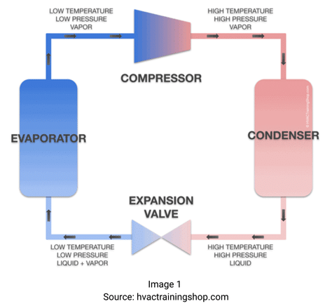
- The four basic components of an air conditioning system are the compressor, condenser, expansion valve and evaporator.
- The compressor receives the coolant from the evaporator as a hot, low-pressure gas and converts it to a high-pressure gas, further increasing the temperature of the coolant in the process.
- This hot, compressed gas is sent to the condenser coil where the heat is released into the outside environment with the aid of a blower. The coolant [LL1] [RC2] releases heat in this process and transitions back to a liquid state.
- As a liquid, the coolant enters the expansion valve, exposing it to a sudden pressure drop, causing it to cool rapidly and convert back to a gas.
- The expansion valve regulates the flow of coolant to the evaporator. Warm air from the equipment room is forced over the cold evaporator coils, allowing the coolant to absorb the heat from the air. This cool air is then forced back into the e-house, and the process continues.
Sensible Heat, Latent Heat and Total Cooling
When sizing an HVAC system in an equipment room, it is important to understand the difference between sensible heat and latent heat, as each influences the HVAC operation in different ways. A basic explanation is below, yet we could write a separate Tech Talk about this topic alone.
Sensible Heat – includes the heat loss from equipment, people, lighting and the thermal loading from the environment. In simple terms, this can be defined as the cooling required to control the temperature in the e-house based on equipment heat loss and air exchanges. Since most e-houses are not occupied, we would not account for people or lighting heat loss in our calculations.
Latent Heat – for this exercise, it will be considered as the moisture or humidity in the air, which needs to be considered for proper cooling.
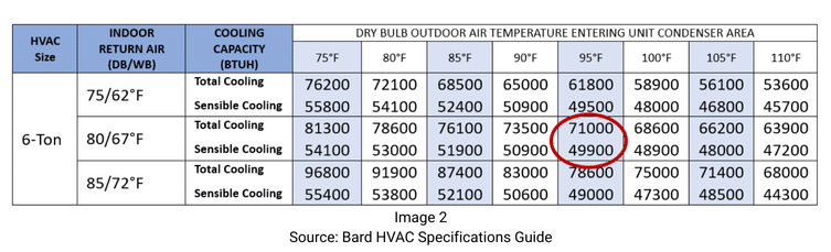
So why is this important? Let’s review the capacity table below, based on a 6-ton Bard HVAC unit. In the 95° Dry Bulb Outdoor Air column, based on 80° indoor return air, the total cooling value for this 6-ton unit is 71,000 BTUs. Yet, when sizing this based on the sensible rating, the unit can only provide cooling up to 49,900 BTUs. As a design engineer, if we use the total cooling value, we would be under-sizing all HVAC applications based on using full nameplate losses for the equipment.
If HVAC sizing was simply a math problem:
- A Watt is a unit of power or energy usage, and a BTU is a unit measuring heat energy.
- 1 Watt = 3.41214 BTU/hr. and 1 ton of cooling = 12,000 BTU/hr.
Based on that math, a 6-ton HVAC should potentially have the capacity to clear 72,000 BTUs of heat (71,000 BTUs in the example above). Yet, as the table above indicates, the sensible cooling value is capped at 49,900 in our example. Most HVAC units have a sensible load to total load ratio in the range of 0.70-0.75. In the example above, the 71,000 BTU value is derated to 49,900, proving the range values.
Also noteworthy is that various brands of HVAC manufacturers have differing efficiency rates and publish different sensible cooling values. Trachte engineers work with different HVAC systems to design the best system performance for initial investment and operational costs.
Heat Loss Considerations
Now that we reviewed basic cooling technology and the importance of using sensible heating in our selection of an HVAC unit, we need to look at the equipment creating the heat inside the e-house.
The engineer sizing the HVAC needs to have a basic understanding of the duty cycle and run time of each piece of equipment inside the e-house in order to properly calculate the heat loss contribution.
In addition to full nameplate heat loss values, the list below includes other data critical to properly size the HVAC system for optimal operation:
- Loading of Equipment – As an example, if a medium-voltage switchgear lineup has a 2000A main breaker and ten 1200A feeders, the heat loss experienced would not be the summation of all those loads. Since the maximum load (and heat) on the incoming equipment is limited to the 2000A rating of the main, in theory, the output load (and heat) could not exceed that value.
- Duty Cycle – If the HVAC engineer designs the cooling capacity based on all equipment running twenty-four hours per day, yet it only runs for an hour each day, the HVAC will be oversized and not function as designed.
- Equipment Correlation – If the system has one load that cannot run at the same time as another load, the heat loss from the higher load should be used for HVAC sizing and not both loads.
- Variable Frequency Drives (VFD)– VFDs are a major source of heat generation in e-houses. If the VFD has a bypass contactor that engages when the motor reaches a set speed or specific process related value, the VFD drive basically stops contributing heat to the e-house space and should not be considered in the cooling design for longer than the time the VFD operates without the bypass contactor.
Other Design Considerations
- Location of the HVAC units is critical for efficient airflow to provide focused cooling at locations where the heat load is the highest. Without the use of ductwork, each HVAC unit will supply cool air and draw return air from where the units are physically located on the wall. Proper design considerations should include locations where the heat concentration is highest, so the heat is cleared efficiently. HVAC units should also be placed to provide sufficient air distribution throughout the e-house space.
- If the heat loss values indicate one HVAC unit will work for the e-house, the engineer still may elect to split the cooling into two units to get better air distribution and to have some level of back-up in case one unit were to fail.
- HVAC redundancy should be planned during the e-house system design to ensure proper space is allocated to allow for the number of units required to cool the space, plus additional units to meet the redundancy requirements of the specification.
- The redundancy specifications we see the most are N+1 – meaning the number of units required to cool the space, plus one more for redundancy, and 100% – meaning the number of units required times 2.
Air temperature sensor placement is critical to ensure the sensor is sampling the return air effectively, yet not impacted by a heat source, the supply-air, or a major source of incoming air like an open door or intake louvers.
Location of the HVAC should be an integral part of the overall design. Factors to consider:
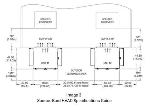
- Proper spacing for outdoor clearance to ensure multiple units mounted adjacent do not impact each other or compromise airflow
- Distance between units should follow manufacturers’ guidelines
- Potential egress paths outside to ensure the HVAC unit is not physically blocking any paths personnel may use
- Discussions with the site regarding the distance to a fence, wall, or other potential site impediments – see Image 3 below.
- Controls are a critical design feature for any HVAC system. From simple thermostats to complex PLC- based controllers and sensors, there are copious options that can aid in the design and operation of the overall system.
- Communication to the system should be considered up front, as many basic systems only allow for limited data through dry contacts. If remote monitoring or control are desired, a system matching the site communication protocol can be incorporated into the units or the temperature controllers.
- Pressurization systems can be combined with the HVAC system to ensure pressurized air is also conditioned. This is another specialized area for the design, factoring in “slight pressure” which is not measured, as well as a system providing full measurement against a water column value with controls to keep the pressure consistent.
- This paper is focused on non-classified areas, yet options exist for purge and pressurized systems that will operate within a classified area.

Conclusion – HVAC Systems Are Not One Size Fits All
Sizing HVAC systems, specifically the cooling required for an e-house, uses a combination of science-based calculations with the art of knowing the application details and characteristics. Each application differs in the environmental location, equipment applied, load profiles associated with each piece of equipment, equipment correlation within the e-house, and requirements for redundancy. Cooling systems should not be considered a one-size-fits-all approach, and each application should include a breakdown of the heat loss calculations, as well as a software output verifying the HVAC applied meets the demands of the heat loss and specifications for the project.
Having the proper amount of cooling at the location and during the time it is needed is key to operational efficiency of complex equipment and improves overall system reliability. Many application engineers over-apply cooling, using a randomly applied safety factor in their calculations. This safety factor should be applied after the heat loss values are calculated and documented against a cooling solution. Excessive safety factors in each HVAC could cause the units to operate improperly and freeze up. Extra cooling capacity should be an engineered part of any installation to ensure the capacity is there as needed, without having a negative impact on the expected daily operation of the system.
Trachte Application Engineers and Designers have extensive experience in the design of cooling systems for sensitive electrical equipment. Our team uses best practices, as well as specific project details and designs, to develop custom-engineered HVAC solutions for all applications. We work to optimize cooling efficiency to protect valuable assets, while helping manage the budget for initial cost, operating efficiency, and expense over the life of the system.
We look forward to engaging with you during the specification phase of your next project to ensure the cooling requirements are well defined based on key and critical operational performance criteria. For more information on cooling considerations or any other e-house application issues, please reach out to your Trachte Account Representative to discuss the specifics of your project.
Download a copy of the Tech Talk Here
The author is Rob Chaffee, Executive Director – Integrated Packaging, nVent TRACHTE